

ADVANCED INTEGRATED
FIRE PROTECTION SYSTEMS
FIRE PROTECTION SYSTEMS

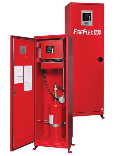
FIREFLEX 1230
Clean Agent Fire Extinguishing Integrated System
The FIREFLEX® 1230 integrated systems are adapted for use in any mission critical facility requiring a clean extinguishing agent that is not only fast and efficient, but also safe for people and the environment. The FIREFLEX® 1230 system uses Novec™ 1230 fire protection fluid manufactured by 3M™. This clean extinguishing agent is at the cutting edge of technology in terms of sustainable development.
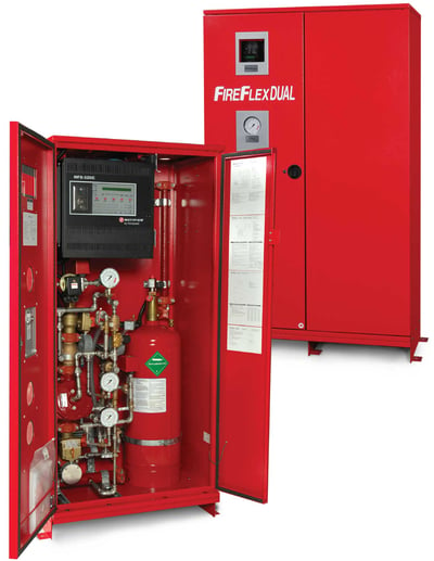
FIREFLEX DUAL
Combined Automatic Sprinkler and Clean Agent Integrated Fire Suppression Systems
Clean agent systems are designed with the purpose of protecting the contents of water sensitive hazards, such as IT or telecom equipment. The FIREFLEX® DUAL provides an integrated solution for dual agent applications.
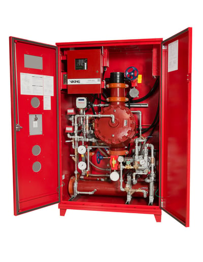
FIREFLEX VACTEC
Vacuum-Based Fire Protection Technology
FireFlex’s VACTEC Vacuum Fire Protection System is a complete FM approved integrated system that offers unique features and benefits such as corrosion mitigation measures and the use of gridded piping network configurations.
ICAF SYSTEM
Compressed Air Foam Systems
The ICAF compressed air foam system is FM Approved as a local application extinguishing system for class B pool fires, spill fires and cascading fires. Available with modular release and compact layout, the ICAF is factory built under ISO 9001 conditions.
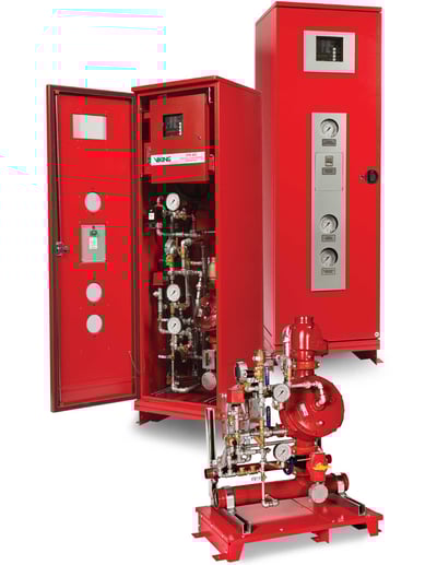
TOTALPAC 3
TOTALPAC® 3 : The Legend
Compact and aesthetic, the TOTALPAC® 3 set the bar for modern fire protection applications. Designed with user-friendly features, the TOTALPAC® 3 units are easy to install and maintain. This is an industry classic that uses the one and only Viking Corp trim valve.
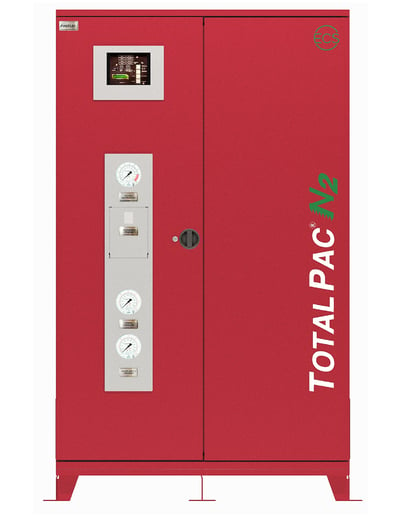
TOTALPAC N2
New : Corrosion Inhibiting Systems
The TOTALPAC® N2 and its nitrogen generator consists of a preaction system trim totally pre-assembled, pre-wired, factory tested and ready to be connected to the water supply and piping network.
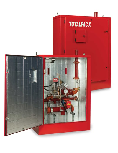
TOTALPAC X
Outdoor Installations and Corrosive Environments
Built for outdoor Installations and Corrosive Environments, the TOTALPAC X system addresses specific industry needs and provides innovative fire protection solutions adapted for challenging applications. Designed with user-friendly features, the TOTALPAC® X units are easy to install and maintain.
TOTALPAC® 3 Simulator
Meet with an expert to simulate various configurations and select the right solution for securing your project.

VACTEC System Calculator
Designing your system to meet your water delivery time requirement when using the FireFlex VACTEC.


Offshore Applications

Aircraft Storage

Fueling Gantry

Fuel Oil Storage

Fuel Pumps

Gas Turbine

Hydraulic Power Pack

Hydraulic Press

Lube Oil Skid

Machinery & Equipment

Power Plant
Power Transformer

Process Room

Pumping Station

Quench Tank

Rolling Mill

Spray Booth

Telecommunications

Server Room

Archives & Banks

Library

Labs

Cold Storage

Mining

Hospital

Pharmaceutical
TOTALPAC® 3 Simulator
Meet with an expert to simulate various configurations and select the right solution for securing your project.
VACTEC System Calculator
Designing your system to meet your water delivery time requirement when using the FireFlex VACTEC.
VACTEC System Calculator
Designing your system to meet your water delivery time requirement when using the FireFlex VACTEC.